The FG9 - EMD's part in the free-piston adventure
Index For This Page
This page was last updated on April 5, 2020.
(Return to Union Pacific Diesels index page)
Manuscript as submitted to Oljefilteret, Nov. 2011
Zsolt Kemény, NOHAB-GM Foundation, Hungary (NOHAB-GM.com)
Overview
Imagine an F-unit with a turbine whine and a loud, slow drumming that shakes one's intestines... Those visiting the Eastern Block in the 1960s may have heard something comparable, the "Taiga Drum", as that crude-sounding diesel-electric was nicknamed in East-German railway slang. Though not by a conventional diesel, but American railroads, at least the Union Pacific, could have topped that sound with a "Prairie Drum", had the FG9 made it into production.
Wikipedia Article
Free-Piston Engine article at Wikipedia
Photos
Photo, EMD FG9 Locomotive (this page)
UP 82 and 82B, illustration by Zsolt Kemény (this page)
UP Letter
Letter from EMD to UP concerning the locomotive (2 page PDF)
EMD Builder Data
Research by Robert Lehmuth, as he compiled a complete record of all locomotives built by EMD, indicates that a possible builder number assigned to the FG9 project was 22006, with an EMD order number of 3199. The builder number sequence puts the unit immediately after the 30 FL9s (EMD 21946-22005) built for New Haven in November 1960.
Research by Larry Russell indicates that the EMD order number for the FG9 gasifier locomotive project was 7270 (cancelled).
Historic retrospective
Coming across records of EMD's FG9 for the first time can be very intriguing, especially in an era where the diesel engine has established itself by a wide margin as the most practicable power plant for internal-combustion railway traction. Today, we are apt to think of only one possible means of transforming fuel to tractive effort: a piston engine transfers work, via a crank shaft, to electric or hydraulic power transmission which, finally, exerts the tractive effort. Past days of railway engineering, however, have seen other power plants and means of transmission as well, so was, initially, the use of a working gas as power transmission medium among the alternatives to be tried for traction.
An early example of such attempts became known as the German Druckluftlokomotive, a solitary experiment of diesel-pneumatic motive power [7]. The Esslingen-built design was fitting a common engineering pattern; the reuse of old principles with a new solution in an effort to rely on tried-and-proven preliminaries wherever possible. Here, a piston engine (a diesel originally designed for a submarine) was driving a two-stage air compressor, and the compressed air performed work in typical steam-era valve gear. Even though some of the losses inherent to compression and expansion were recovered by an exhaust gas heat exchanger, efficiency and overall performance of the locomotive were far from convincing. Consequently, the prototype was short-lived: built in 1927 as V 3201 and later renumbered V 120 001, the unit lasted in service until 1933 only, and German railways turned to hydraulic and electric power transmission instead.
The failure of the diesel-pneumatic may, however, elicit an afterthought: would the use of a working gas not be more efficient if the engine exhaust directly delivered the energy to a working stage? If the engine does not perform substantial work via the crankshaft, the exhaust gases must, consequently, still convey much of the energy released in combustion; how about using this medium to feed valve gear or a turbine?
Similar thoughts must have crossed the minds of engineers at Götaverken in Sweden, conceiving a gas generator and turbine power plant. In this case, a more or less conventional piston engine was employed which delivered work at the crankshaft to drive its own compression stage only. The remaining combustion energy was still carried by the exhaust gas, and was delivered to a power turbine.
Several examples of this design were already in service in ship propulsion before the first railway application came about in 1933: a NOHAB-built locomotive with a Götaverken gas generator and turbine power plant, employing purely mechanical transmission between turbine and driving wheels [24]. This prototype held its ground much better than the German diesel-pnemuatic: despite being a one-off experiment, regular service lasted until 1937, and at one point, the original 1'B1' axle arrangement was even modified to 1'C1' to permit its use on lines with lighter axle loads. After years of railway service, the power plant worked on for more than a decade; in a tug boat as many other examples of Götaverken's power plants did right away.
The same design principle was later replicated in one more Swedish locomotive: the Motala-Götaverken-built T1 (T11) of 1955 [24]. Later on, another experiment by Motala Verkstad followed (T7) which, however, combined the exhaust-driven gas turbine with a crankshaft-driven hydraulic transmission [24], implementing the 1958 patent of Leonhard Geislinger [10].
Possible forms of gas generators, however, are not restricted to reciprocating engines with a crankshaft; producing high-pressure exhaust does work even with purely linear piston motion. This idea was pursued in the early 20th century by Raúl Pateras Pescara who conceived a free-piston engine and covered a wide class of such designs in a patent issued 1928 [15]. While free-piston engines allow a variety of different configurations, they all share some characteristics:
- The motion of the piston(s) is purely linear (and usually also performs some of the work needed to keep the engine running, most importantly compression).
- After completion of ignition and expansion, the piston(s) are returned and forced into compression in the combustion chamber by a rebound device, such as a spring, an array of actuator coils or a gas cushion formed by a bounce chamber.
- The stroke length of the pistons is not rigidly restricted as in crankshaft-equipped cases; it may vary depending on fuel-specific ignition conditions, as well as the behavior of the rebound device and the load (e.g., a turbine, a hydraulic pump or a linear generator).
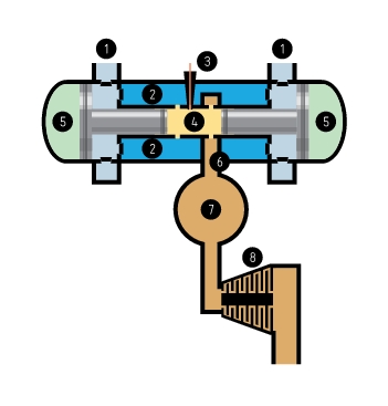
Figure 1: Schematic layout of a free-piston gasifier of an inward-compressing type (compression of air is taking place while pistons move inward), driving a gas turbine. 1: air intake, 2: air box, 3: fuel injector, 4: combustion chamber, 5: bounce chambers, 6: exhaust outlet, 7: surge tank, 8: gas turbine.

Figure 2: The free-piston gasifier operates basically as a two-stroke engine with compression (a) and combustion/expansion (b) phases alternating.
With these principles, even a single-piston configuration is feasible, however, attention initially turned to a single-cylinder opposed-piston design. Here, the motion of the pistons was synchronized by a mechanical linkage that still allowed variable stroke length but promised low vibration if the piston pair was adequately balanced. First commercial application of the free-piston design were air compressors where the engine pistons were directly actuating one or more compressor stages; some of these, the lineage of Hugo Junkers' development, even made it into WWII submarines due to their simplicity and trouble-free operation.
Pescara's engine went to work on a larger scale around the late 1940s when, coupled to a turbine, free-piston gasifiers presented a feasible power plant for stationary power generation, ship propulsion, and, finally, railway traction and automotive application.
The advantages of the gasifier and turbine power plant were very promising. The gasifier was virtually omnivorous and could, owing to its variable stroke length and compression ratio, adapt to almost any liquid fuel; including the residue oils that were still very cheap at that time. With unbelievable compression ratios up to 1:50, its combustion conditions were far better than those in single-shaft gas turbines, and let engineers hope for much higher thermal efficiency. Mixing the exhaust with air could lower the exhaust temperature at no mentionable energy loss, allowing less resistant but cheaper materials to be used for the turbine blades. Separating combustion from working stages would also allow the combination of several gasifiers and several turbines into one system, improving availability figures for high-power applications as power stations and large ships. Unsolved and unknown problems did exist but appeared to be minor challenges compared to the advantages that did address several problems of the time; no wonder the engineering community expected the dawn of a new era in internal-combustion technology: a free-piston revolution [19].
The most significant leader in these developments was France, notably, the companies SIGMA (Société Industrielle Générale de Mécanique Appliquée) and SEME (Société d'Etudes Mécaniques et Energétiques). The SIGMA GS-34 was one of the most widespread gasifier types for the higher power range; its nominal output of 1200 HP made it interesting for railway application as well [16].
The stage was set for the latter in early 1952, as the 040-GA-1 prototype went on first road tests [4, 24]. Built by Renault, the locomotive was equipped with a single SIGMA GS-34 opposed-piston gasifier and a Rateau-built six-stage turbine, driving all four axles of the unit via mechanical transmission. In subsequent years, the prototype underwent extensive road tests, and several modifications were carried out to refine the design. Both diesel fuel and heavy oil were successfully used, with peak thermal efficiency being around 33%, roughly twice that of a single-shaft gas turbine and heat exchanger power plant of the time, and almost as much as a conventional diesel engine and electric transmission would present. Altogether, the 040-GA-1 succeeded in showing that it was technically feasible to build and operate a free-piston-turbine locomotive.
Spurred on by the success of the 040-GA-1, two more locomotives followed: the six-axle prototypes of the 060-GA series, one in 1959 and a second one in 1961, each equipped with two independent gasifier and turbine power plants driving one of the bogies via switchable mechanical transmission [4, 24].
The conquest of the free-piston engine, especially in the power range of several thousand HP, did not remain within French borders; many other countries, including the UK, the USA, and the SU, manufactured free-piston gasifiers for commercial application, mostly in ships, power stations and pump stations on long-distance pipelines. Nevertheless, only one further example of an implemented free-piston locomotive is known: the Soviet prototype GT101-001, designed for a projected output of 3000 HP, employing four gasifiers feeding the same five-stage turbine [18]. Following a redesign, replacing the electric transmission with a lightweight hydraulic alternative, the experimental unit was completed in 1960 by the diesel works in Lugansk, with the Bryansk works delivering the turbine. From 1961 on, road tests were carried out, resulting in extensive rebuilding of the gasifiers, yet, no further units of the type were built.
Free-piston research at GM
Many American companies worked to secure their place in an envisaged free-piston revolution, and beside (Baldwin)-Lima-Hamilton, GM was one of those conducting considerable research in the high-horsepower domain. GM did, in fact, not remain in the high-horsepower range: GM products coming in all possible sizes inspired researchers to examine how the free-piston engine would perform in several ranges of power and size.
The smallest gasifier to see road tests was the GMR-4-4 "Hyprex" engine [12, 25], a unique siamesed unit comprising two cylinders working in opposite phases by means of a pneumatic dephaser [6]. Coupled to a five-stage power turbine, the power plant was small and light enough for an experimental road vehicle of sports-car size: the XP-500 [14]. Unveiled in 1956, the car was tested on the most different, often exotic, fuels, was examined for fast turbine response and part-load behavior, but remained a solitary piece, rather a laboratory on wheels than an automotive prototype.
The top of the spectrum was ship propulsion, having acquired the license for the GS-34 gasifier, GM developed it into their own large-scale design, the GM-14, and repowered the Liberty Ship William Patterson with a gasifier and turbine assembly. The six independently operating gasifiers were feeding two reversible turbines, coupled to the propeller shaft via fixed reduction gear. Power output could be varied by valves controlling the gas flow of the turbines; also, gasifiers could be shut down and started separately to match the load presented by the turbine. Starting 1957, the ship covered over 140,000 miles on voyages and delivered more than ten thousand hours of operating experience [21].
The GM-14 gasifiers for the William Patterson were manufactured by Cleveland Diesel Engine Division, the non-locomotive business remainder of the former Winton Engine Corporation, itself fully merged into Electro-Motive Division by 1962. The close relation of the Cleveland Division and EMD might raise a question: Would they not try a GM-14 in a locomotive? Indeed, this was about to happen, in what became known as the FG9 project.
The FG9 project
The 1950s were an era of transition on the railroads: though running on borrowed time, steam was still present, and even if diesel seemed the ultimate internal-combustion choice for non-electrified lines, it was not absolutely certain that the next years or decades would not come up with a more efficient, cheaper-to-operate alternative. Fuel prices were actually one of the key drivers of a search for other technologies,a locomotive burning cheaper fuel for the same output would have meant serious competition to the diesel.
Turbine-powered locomotives emerged as a response: although far less efficient than a diesel, the cost of the heavy oil they burned for the same performance was low enough to justify their use (well-noted, along with maintenance advantages of fewer separate units for the same power).
The free-piston and turbine power plant was also able to run on low-grade fuels, however, with an efficiency comparable to that of a diesel! Would that not present an attractive alternative? Some American manufacturers did plan to meet this promise: (Baldwin)-Lima-Hamilton, for example, invested considerable effort in their own track of free-piston research, their projected gasifier differing much from the GS-34 and GM-14 lineage, and introducing such innovative ideas as turbocharging [22]. In the early 1950s, news surfaced about plans of a free-piston-turbine-electric, with the Pennsylvania Railroad being a potential customer [19]. BLH's early departure from the railroad business, however, blighted these prospects for good.
Starting 1957, numerous technical journals reported EMD's plans of employing free-piston and turbine power plants for railway traction [9]. At the same time, a patent application was filed at the U.S. Patent Office. Issued, finally, 1960 as U.S. Patent No. 2949541 [1], it clearly shows that by 1957, EMD's engineers already had a ripe picture of what they intended to do, and how they intended to tackle the engineering challenges inherent to railway traction while reusing tried-and-proven solutions where this meant no hindrance to innovation.
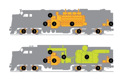
Figure 3: Much of the power transmission, air systems and auxiliaries of contemporary FL9 would have been reused in the FG9. 1: EMD 16-567C prime mover, 2: D12 main generator and D14 auxiliary alternator, 3: D37 traction motors, 4: 18kW DC auxiliary generator, 5: air compressor, 6: DC-driven air compressor, 7: GM-214 free-piston gasifier, 8: power turbine and gearbox.
EMD's free-piston locomotive, too, would have used electric transmission, just as BLH's machine would have done, both presenting a contrast to the prototypes implemented in Europe. The FG9 was to employ an "off-the-shelf" D12-D14 main generator and alternator assembly, the usual DC auxiliary generator for excitation and battery charging, D37 traction motors, and the three-phase traction motor blowers and radiator fans of the time. All these were arranged, the way one may expect, in an FL9 carbody which, riding on B0'A1A' trucks, provided generous space... for the "strange contraption" that would have meant the novelty in this locomotive.
Here is where the interesting part begins: the gasifier, placed above the rear truck, was a GM-214, a siamesed version of the GM-14, deploying the pneumatic dephaser concept of the automotive-size GMR-4-4 on a much larger scale. In this arrangement, both cylinders are started in the same phase, by flooding the bounce chambers with pressurized air. Once the critical first stroke is completed in both cylinders, the pneumatic dephaser cares for establishing an opposed-phase firing within just a few piston strokes. In continuous operation, this distributes both the exhaust blasts and the intake pulses of the two cylinders as evenly as possible, reducing one of the critical burdens of free-piston gasifiers. Although the automotive-scale GMR-4-4 did well without much of a recipient tank smoothing out the exhaust pressure blasts, a much more powerful GM-214 was likely to require one.
The exhaust of the gasifier unit was fed into a turbine that was coupled to reduction gear, driving the main generator/alternator and auxiliary generator in the speed range of the normal diesel-driven operation they were designed for. In the case of the diesel, there is one more component rotating at the same speed as the prime mover: the air compressor. Although documents surfaced so far do not describe the air system of the FG9 in detail, it can be assumed that here, the practice of the dual-mode FL9 was copied: employing an off-the-shelf air compressor driven by the prime mover (coupled to either the gear box or the main generator in the case of the FG9) to cover regular road service, and a smaller auxiliary compressor driven by a DC motor (for third-rail operation in the FL9, and for preparation of gasifier startup in the FG9, powered by the batteries in the latter case).
If the FG9 had entered production, spotting guides would have certainly listed two external giveaway features: the raised roofline accommodating 16 radiator cores instead of 10 for standard F-units, and the large fuel tank assembly, providing space for approximately 300 gallons of diesel fuel, and 1100 gallons of heavy oil. As with the GE turbines of the era, the locomotive would have been started and shut down while running on diesel fuel, but road service would have used heavy oil once proper temperature was reached.
Most interesting about the FG9 design, however, was the control of its power plant [1]. In typical railroad use, an internal-combustion prime mover of any kind must cope with two challenges: i) longer intevals of idle and part-load operation, and ii) frequent and fast changes in required prime mover output. In addition, brief periods of "no power" requirement can occur, e.g., during traction motor field shunt or series-parallel transitions, as well as wheel slip mitigation. This differs substantially from the slow changes and long constant-power operation in marine application, and it may be difficult to adapt a ship's power plant or stationary power generation device to the stress posed by railroad use.
Consequently, EMD paid much attention to cover a wide range of output power with fast response, including prolonged idling. To this end, a special control throttle was designed: it allowed a part of the exhaust to be recirculated into the combustion chamber at idle or low output, while during higher-power operation, gasifier performance was controlled by the amount of fuel supplied. The double-action throttle proposed in the EMD patent was stepless; nevertheless, it would have been easy to set it in discrete steps by a solenoid and triangle plate mechanism replicating the one commonly applied in engine governors, thereby allowing the FG9 to run in MU with conventional motive power.
The turbine, not suited too well for some railroad-related conditions per se, presented another challenge. During normal operation, it would have been advantageous to maximize turbine efficiency by keeping its speed in a range where gasifier exhaust could enter without suffering a shock. EMD mastered this in an elegant way, by reusing the existing load regulator, by that time a standard component of every diesel-electric. Since the introduction of Hermann Lemp's original setup [13], main generator excitation was varied to match generator load to prime mover output, in the FG9, the same would have been done to keep the turbine speed within a range preferable for the given gasifier performance. Well-noted, none of the hydraulic or mechanical transmissions could have done this so precisely as in the FG9, implying superior efficiency of the FG9 for large sections of part-load operation.
"Exceptions" were also covered: during idle, turbine speed was controlled by a simple flyweight governor, while "no power" intervals and overspeed emergency actions would have been handled by fast-acting bypass valves leading gasifier exhaust around the turbine.
All this is very impressive, one may think. In fact, the only thing more impressive could have been a lashup of four or five FG9 A and B units in Union Pacific paint battling steep grades and endless miles of track, yes, surviving records do attest the interest of UP in the FG9. Knowing UP's typical power demand of the era, as well as the expected output of the FG9 of roughly 2000 HP, UP may have even ordered B units, as was the case with cab and hood diesels likewise. Negotiations between EMD and UP were going on, as did the news reports promise first road tests in late 1959 [8].
Yet, it did not come to that: the FG9 project was abruptly canceled in the second half of 1959. Records surfaced so far do not allow the exact identification of reasons, nevertheless, there are well-documented parallels in free-piston history that allow an "educated guess". Most important in this context are the evaluated journeys of the GTS William Patterson [21] which deemed free-piston propulsion generally suitable for marine use but shed light on drawbacks which could become much more of an issue in railway traction:
- An output in the order of magnitude of 1000 HP per cylinder implies immense pressure blasts. The exhaust pulses were muffled by the surge tank, the turbine and an optional exhaust silencer; the same could not be said about fluctuations on the air intake side. In the case of the GTS William Patterson, two major redesigns were needed to finally solve the problem of intake-related vibrations in the engine room and insufficient air supply of neighboring gasifiers. The resulting assembly of vestibules and pipes was so voluminous that it vastly transcended any space possibly offered by a locomotive carbody. Limits of intake muffling were faced in the French prototypes as well, as evidenced by reports of extreme noise levels. Could it have been, by chance, the hellish noise that earned the 060-GA the nickname Belphegor? The BLH concept of turbocharging may have reduced these drawbacks to some degree, without any reported prototype, this remains, however, mere speculation.
- Independently running gasifiers operating at almost the same frequencies caused interference phenomena, so-called beat waves. These can have especially unpleasant consequences if multiple gasifiers feed a common load device (the turbine, in our case). This, in turn, would present a serious hindrance to building high-horsepower locomotives in the power range of, say, the GE gas turbines.
- Free-piston technology presented "no free lunch" regarding costs: the apparatus required somewhat more intense maintenance as-is, or would have called for a longer period of technical refinement and evolution of diagnostics and on-the-road troubleshooting know-how, at the cost of considerable time and financial investment (that has already been put into the diesel by that time).
Most of the disillusioning problems peaked in 1959, around the time as EMD and UP were still negotiating parameters and modifications to the proposed FG9 design. It is, perhaps, not far from reality to assume that findings gained aboard the William Patterson indeed played a substantial role in abandoning the project.
The economics of operation, too, may have added some counter-argument, a revenue-earning railroad does have to keep an eye on numbers, after all. Changes in the petrochemical industry soon made heavy oil and residue prices rise (remember how quickly the GE turbines became uneconomical to operate) and shifted the structure of the fuel market.
In the years to follow, the development of conventional internal-combustion engines annulled most of the initial advantages of the free-piston and turbine power plant: diesels, for example, became more tolerant to varying fuel quality, or single-shaft gas turbines, to a major part due to the booming aerospace industry, became more efficient and less sluggish in response. By the early 1960s at latest, these changes were visibly underway, putting off any possible comeback of free-piston technology for quite a while if not for all times.
What happened, then, to existing prototype locomotives and all the high-horsepower applications in ships and stationary plants? They were gradually phased out, replaced by modern internal-combustion technology of the conventional kind.
The French 060-GA-1 and 060-GA-2 were dragging on in service for not more than half a decade before they were stopped. Eventually repowered by a pair of conventional Pielstick diesel engines, at least one of them remained for a lease of useful life in maintenance-of-way service and, finally, in preservation. The Soviet test unit, the only railway example of independent gasifiers feeding a common power turbine, completed some road tests but did not live up to the expectations and sank into oblivion in a matter of years.
Most of the stationary and marine applications lasted another decade if not even less, and last to remain were the pump stations on long-distance pipelines where conditions for long-term stable operation were best of all tested fields of use. For the opposed-piston type of the free-piston gasifier, so it seemed, history ended the way it began: in a thin market niche of compressor applications.
An epilogue: research goes on
One may say, the free-piston revolution of the 1950s was over before it really started. There are, however, inventors and researchers who would tell otherwise. Since the 1980s, new free-piston designs were conceived [3, 5, 17, 23], this time on a smaller scale. They promise to eventually overcome the disadvantages of the ancestral opposed-piston gasifiers:
- Most of the new designs employ a single moving piston with twin combustion chambers, practically acting as each other's rebound devices. The resulting arrangement is mechanically much more simple and less maintenance-intensive than the linkage-synchronized opposed-piston gasifier. Also, issues like valve design and contact surface treatment were addressed, each coming a little closer to a practicable free-piston power plant.
- Instead of a turbine driven by exhaust gases, work is performed directly by the piston, or a device rigidly attached to it. This may be a hydraulic pump, an air compressor or an array of permanent magnets moving inside coils of a linear generator [20]. By discarding the turbine, overall efficiency can transcend that of today's rotating engines by a remarkable margin, values approaching 50% are in sight or have already been measured [11, 26].
- Some solutions envisage improved control of piston motion, primarily those coupled to a linear generator. Here, intervention via generator coils [11] can facilitate optimal combustion, synchronization with other cylinders, better part-load behavior, overcoming many limitations inherent to the 1950s designs.
- Recent advances in design and construction of miniature mechanical devices can very well allow the development and low-cost mass-production of free-piston engines on extremely small scales, going far beneath the dimension limits of earlier decades [2].
While, even after 2-3 decades of research, none of these developments have yet appeared at large in production, it is not entirely unlikely that small-scale free-piston devices will get ahead of competing technologies, such as fuel cells, and find their own proven fields of application. Will emergency phones, then, run on free-piston linear generators burning lighter fluid or butane gas? Or, to conclude with a more fitting vision: will a pair of exotic brass FG9s, say, UP 82 and 82B, pull a 1960s freight consist on our layout at home, powered by miniature free-piston generators?
Acknowledgement
The author would like to thank Philip Hom for providing a photograph of the FG9 locomotive for publication, and Samuel E. Cockerill and Edward Haynes for recommendations on background literature.
References
[1] A.N. Addie, H.A. Williams Jr., H.C. Lafferty (General Motors Corp.): Power Plant Control. U.S. Patent No. 2949541, published Aug. 16, 1960.
[2] H.T. Aichlmayr: Design Considerations, Modeling, and Analysis of Micro-Homogeneous Charge Compression Ignition Combustion Free-Piston Engines. Ph.D. Thesis, University of Minnesota, 2002.
[3] D. Carter, E. Wechner: The Free Piston Power Pack: Sustainable Power for Hybrid Electric Vehicles. SAE Paper 2003-01-3277, 2003. DOI 10.4271/2003-01-3277
[4] G. Charmantier, J. Banaudo: Les locomotives diesel de ligne de la première génération, No. 1. Ed. du Cabri, ISBN 9782908816136, 1993.
[5] S.E. Cockerill (Libertine FPE Ltd): Free Piston Engine. WIPO Patent WO/2011/077119A2, published Jun. 30, 2011.
[6] R.M. Cole (General Motors Corp.): Free Piston Engine Dephaser System. U.S. Patent No. 3116723, published Jan. 7, 1964.
[7] J. Feihl: Die Diesellokomotive-Aufbau, Technik und Auslegung. Transpress Verlag, Stuttgart, 1997. ISBN 9783613710603
[8] Free Piston Nears Road Test. Railway Locomotives and Cars, Vol. 133 No. 7, pp. 24-25, Jul. 1959.
[9] GM Tech Tests Free-Piston Engine. Railway Locomotives and Cars, Vol. 131 No. 5, p. 10, May 1957.
[10] L. Geislinger: Arrangement for transmitting the power output of combustion engines to the wheels of a vehicle or the like. U.S. Patent No. 2848866, published Aug. 26, 1958.
[11] M. Gräf, P. Treffinger, S.-E. Pohl, F. Rinderknecht: Investigation of a high efficient free piston linear generator with variable stroke and variable compression ratio. WEVA Journal Vol. 1, 2007, pp. 1-5.
[12] A.W. Judge: Small Gas Turbines and Free Piston Engines. The MacMillan Company, New York, 1960.
[13] H. Lemp (General Electric Co.): Self-Propelled Vehicle. U.S. Patent No. 1589182, published Jun. 15, 1926.
[14] H. Manchester: 'Engine of Tomorrow' Goes to Work Today. Popular Science, Vol. 171 No. 3, pp. 138-141, 294, Sep. 1957.
[15] R.P. Pescara (Pescara & Raymond Corp.): Motor-Compressor Apparatus. U.S. Patent No. 1657641, published Jan. 31, 1928.
[16] F. Picard, R. Huber: Utilisation des combustibles lourds -- l'emploi des générateurs à pistons libres en traction ferroviaire. Proc. of the 3rd World Petroleum Congress, The Hague, 1951, pp. 130-142.
[17] S.-E. Pohl: Der Freikolbenlineargenerator - Theoretische Betrachtung des Gesamtsystems und experimentelle Untersuchungen zum Teilsystem der Gasfeder. Ph.D. Thesis, Deutsches Zentrum für Luft- und Raumfahrt, 2007.
[18] V.A. Rakov: Locomotive and Motor Car Motive Power of the Railways of the Soviet Union (title originally in Russian), 1956-1965, Ed. Transport, Moscow, 1966.
[19] J.D. Ratcliff: Revolution of the Free-Piston Engine. Popular Mechanics, Vol. 94 No. 3 pp. 114-118, 248-252, Sep. 1950.
[20] F. Rinderknecht, H.-G. Herzog: Calculation of a linear generator for a hybrid vehicle concept. In: Proc. of XIX International Conference on Electrical Machines (ICEM), 6-8 Sep. 2010, pp. 1-5, DOI 10.1109/ICELMACH.2010.5607780
[21] D.H. Specht: Evaluation of Free Piston-Gas Turbine Marine Propulsion Machinery in GTS William Patterson. SAE Paper 620280, 1962. DOI 10.4271/620280
[22] H.G. Spier: Supercharging in the Free-Piston Cycle. SAE Paper 590035, 1959. DOI 10.4271/590035
[23] F. Stelzer: Device for transporting fluids. European patent No. EP1483488, published 8 Dec., 2004.
[24] W. Stoffels: 30 Jahre Gasturbinenlokomotive. Private ed. of the author, 1964.
[25] A.F. Underwood: The GMR 4-4 "Hyprex" Engine -- A Concept of the Free-Piston Engine for Automotive Use. SAE Paper 570032, 1957. DOI 10.4271/570032
[26] P. Van Blarigan: Rapid Combustion Electrical Generator. Reciprocating Engines Peer Review, Illinois, 2002.


###